

Opening: why a framework matters for fleet charging projects
When planning a high-frequency fleet charging hub, a repeatable framework turns guesswork into deliverable outcomes. This article outlines a pragmatic, engineer-facing pathway to provision a custom 10 kWh battery storage module — the kind often used for short-duration buffering, peak shaving, or fast-response load management. For project managers and systems integrators, thinking in terms of modular commercial battery storage simplifies procurement, reduces risk, and aligns the technical scope with operational goals.
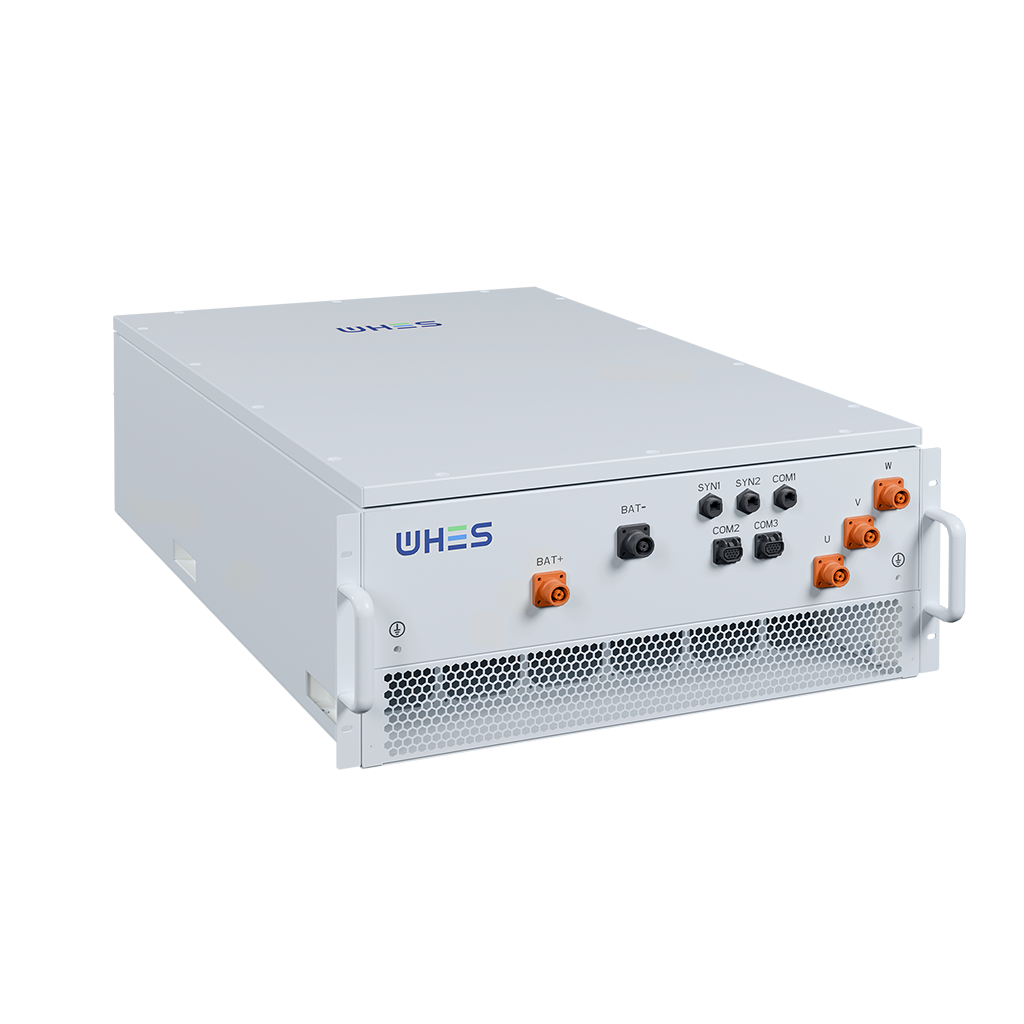
Step 1 — Define operational drivers and constraints
Begin with the use case: is the pack for smoothing charger inrush, providing V2G support, or shaving demand charges? Translate that into measurable targets: power (kW), energy (10 kWh baseline), charge/discharge cycle count, acceptable depth of discharge (DoD), and response time. Also list site constraints: available real estate, thermal limits, and utility interconnection rules. These inputs determine whether a compact 10 kWh system suffices or whether parallel modules are needed to meet peak power requirements.
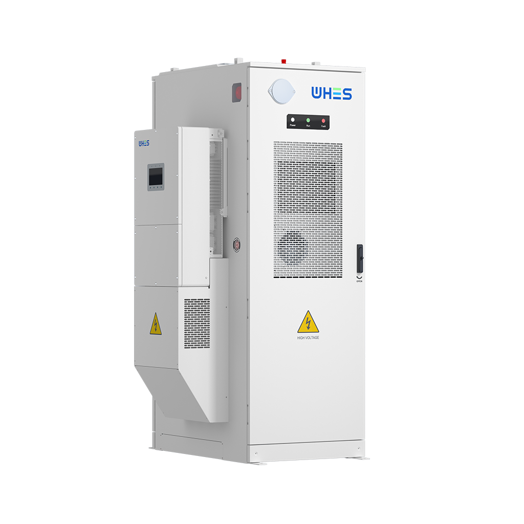
Step 2 — Sizing and performance assumptions
Size the battery not only by energy but by real duty cycle. A 10 kWh pack can supply 10 kW for roughly one hour at full discharge — but in practice you will budget for usable energy based on DoD and round-trip efficiency. Include margin for state-of-charge (SoC) management and reserve for emergency events. Conservative assumptions here prevent early degradation and allow realistic BMS strategies to extend calendar life.
Step 3 — Integration architecture and power electronics
Decide whether the battery will sit behind a single inverter or use distributed bi-directional converters near each charger. Integration choices affect inverter count, control complexity, and how smoothly the system can island during outages. Consider the communications stack — Modbus, CAN, or IEC 61850 — to ensure the BMS and chargers exchange SoC, fault, and command data reliably. If you plan solar co-located generation, coordinate PV inverter controls to avoid conflicting ramp commands.
Step 4 — Controls, software, and grid services
Control logic must prioritise local objectives: sustained charger availability, minimal demand charges, or providing ancillary services. Implement energy management rules that account for tariff windows and predicted load — simple rule-based controllers work well, but machine-learning models can improve forecasts at scale. Also plan for grid-interactive behaviours: frequency response, islanding, and ride-through. These features are essential when the hub supports critical municipal or transit operations.
Real-world anchor: lessons from port electrification pilots
Large electrification pilots — for example, initiatives around the Port of Los Angeles — have shown that even modest buffer systems materially reduce peak demand and ease utility approvals. Operators there reported that staged battery deployments eased grid upgrades and allowed chargers to come online faster. Such real-world trials underline a pragmatic truth: start with operational metrics and scale the system iteratively rather than aiming for a single all-encompassing design.
Common mistakes to avoid
Teams often make three repeated errors: underestimating thermal management needs, over-optimistic cycle-life forecasts, and unclear acceptance tests at handover. Thermal issues accelerate cell fade; please budget dedicated cooling and monitoring. Similarly, define acceptance criteria that tie to measurable BMS telemetry and inverter behaviour — do not rely on visual inspection alone. And always test with real chargers to validate responses under realistic harmonics and inrush conditions — this prevents surprises on commissioning day.
Procurement and vendor selection
When assessing suppliers, evaluate their demonstrated cycle-life data, warranty carve-outs for calendar ageing, and software update pathways. Look for vendors who support modular expansion and provide clear interoperability documentation for inverters and chargers. For sites pairing storage with solar, a supplier experienced in commercial solar battery storage brings practical lessons about PV-battery control co-ordination and simplified interconnection.
Advisory: three critical evaluation metrics
1) Lifecycle cost per usable kWh — not just upfront price: include degradation, replacement cadence, and efficiency losses. 2) Response and control latency — millisecond-to-second responsiveness matters when supporting high-frequency chargers and grid signals. 3) Interoperability maturity — proven integration with chargers, inverters, and BMS telemetry reduces commissioning time and operational headaches.
Measured against these metrics, you will see which designs truly meet service-level targets and which are merely attractive on paper. For many fleet operators, the modular, turn-key approach offered by partners like WHES translates the technical framework into operational uptime and predictable economics. —